

Injection Mould Tool Production
expert toolmakers
As UK-based precision engineers, Cobra Tool & Die have the capacity to handle part or all of the production process for injection mould tools on-site.
Each stage of your project can be managed in-house at our premises in Portsmouth, from product development, product design and prototype tooling to production tooling, servicing and rapid repairs.
Mould Tools for Plastic Injection Tool Mouldings have always been the backbone of our business. As expert toolmakers with decades of experience, our knowledge and expertise is second to none and is highly regarded by our customers.
Why Choose Our Mould Tool Production?


INJECTION MOULD TOOLING FAQs
Some frequently asked questions about injection mould tool production
PARTS OF THE INJECTION MOULD TOOL
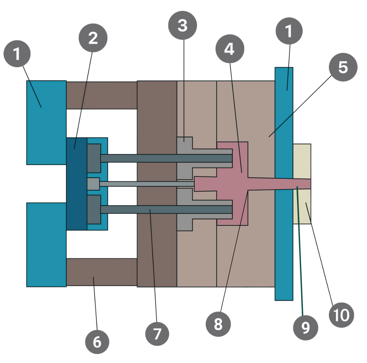
The diagram shows a section through the centre of a basic injection mould tool.
1. Back plate (fixed half / moving half)
The back plate is a mounting surface for the components of the injection mould, attaching the mould to the injection moulding machine. The mould halves need to come together accurately during the injection moulding process, so the back plate serves to provide stability, aligning the halves correctly.
2. Ejector plate
The role of the ejector plate is to support the ejector pins (see point 9) and to move them forward to eject the product from the injection mould tool once it has solidified.
3. Core
The core makes up the internal shape of the product and is part of the lower half of the mould tool. It works together with the cavity to define the final shape of the product during plastic injection moulding. If there are internal features or hollow parts of the product, the core is the part of the mould tool that forms these.
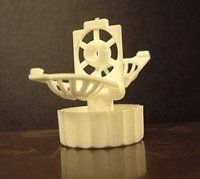
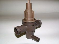
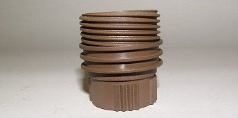
4. Product
The product is the final component that is produced by the injection moulding process. The product can be a small, intricate part or a larger, complex component; products manufactured from moulds produced at Cobra Tool & Die range from high-spec seals and gaskets to consumer goods.
5. Cavity
The cavity is the hollow part of the injection mould that shapes the product. The upper half of the mould forms the cavity, which is where the molten plastic is injected. The cavity of the plastic injection mould must be designed and finished to a high standard in order to produce high-quality components.
6. Spacer block
This maintains the required distance between mould plates during the plastic injection moulding process. The mould must close uniformly, with all parts correctly aligned.
7. Ejector pin
The ejector pin pushes out the product from the injection mould once it is solid.
8. Runner
A pathway that directs the molten plastic from the sprue into the cavity, designed to balance the flow.
9. Sprue or feed
Molten plastic enters the mould via the sprue, also known as the feed. This is the channel that connects the injection moulding machine nozzle to the runner system. The flow rate and pressure of the injected material is affected by the design of the sprue itself.
10. Location ring
The location ring locates the tool in the press. This makes sure that the mould is positioned correctly and aligned with the nozzle of the injection moulding machine.


Contact Us
If you would like to discuss your toolmaking needs, whether that’s innovation, concept design, new tooling or repairs, get in touch with us to find out more about what we can offer you. Give us a call, or why not pop in and see us!